D flip-flop
Clocked always blocks should use non-blocking assignments: <=.
Solution
module top_module (
    input clk,    // Clocks are used in sequential circuits
    input d,
    output reg q );//

    // Use a clocked always block
    //   copy d to q at every positive edge of clk

    always @(posedge clk) begin
        q <= d;
    end
endmodule
D flip-flops
Solution
module top_module (
    input clk,
    input [7:0] d,
    output [7:0] q
);

    always @(posedge clk) begin
        q <= d;
    end
endmodule
DFF with reset
Solution
module top_module (
    input clk,
    input reset,            // Synchronous reset
    input [7:0] d,
    output [7:0] q
);

    always @(posedge clk) begin
        if (reset) begin  //复位
            q <= 8'b0;
        end else begin
            q <= d;
        end
    end
endmodule
DFF with reset value
正触发: posedge
负触发: negedge
Solution
module top_module (
    input clk,
    input reset,
    input [7:0] d,
    output [7:0] q
);

    always @(negedge clk) begin
        if (reset) begin
            q <= 8'h34;
        end else begin
            q <= d;
        end
    end

endmodule
DDF with asynchronous reset
异步复位
The only difference in code between synchronous and asynchronous reset flip-flops is in the sensitivity list——将复位信号写入敏感列表中。
Solution
module top_module (
    input clk,
    input areset,   // active high asynchronous reset
    input [7:0] d,
    output [7:0] q
);

    always @(posedge clk, posedge areset) begin
        if (areset)
            q <= 0;
        else
            q <= d;
    end

endmodule
DFF with byte enable
wire vs. reg
| 特性 | wire | reg |
|---|---|---|
| 存储功能 | 无存储功能,数值由驱动源决定 | 有存储功能,能保持当前值直至下一次赋值 |
| 赋值方式 | 只能使用连续赋值(如assign语句) | 只能在initial或always块内赋值 |
| 使用场景 | 用于连线、组合逻辑输出 | 用于时序逻辑(如触发器)、组合逻辑中的中间变量 |
| 默认初始值 | 默认值为z(高阻态) | 默认值为x(未知状态) |
下面通过两段代码示例,直观展示wire和reg的使用差异:
// wire的使用示例
module wire_example;
    reg a, b;      // 输入信号定义为reg类型
    wire out;      // 输出信号定义为wire类型

    // 连续赋值,out的值会随着a和b的变化而立即改变
    assign out = a & b;

    initial begin
        a = 1'b0; b = 1'b0;
        #10 a = 1'b1;
        #10 b = 1'b1;
    end
endmodule
// reg的使用示例
module reg_example;
reg clk, rst, in;
reg out; // 输出信号定义为reg类型,因为在always块中被赋值
// 时序逻辑:在时钟上升沿更新out的值
always @(posedge clk or posedge rst) begin
if (rst) begin
out <= 1'b0; // 复位时将out置为0
end else begin
out <= in; // 时钟上升沿时将in的值赋给out
end
end
initial begin
clk = 1'b0;
forever #5 clk = ~clk; // 生成周期为10的时钟信号
end
endmodule同步低有效复位(resetn)
- 同步性:复位仅在 时钟上升沿 生效(异步复位会在复位信号变化时立即生效,此处为同步)。
- 低有效:
resetn = 0时触发复位,resetn = 1时正常工作。
字节使能(byteena[1:0])
- 分组控制:16 位数据分为 低字节(
d[7:0],由byteena[0]控制)和 高字节(d[15:8],由byteena[1]控制)。 - 功能:仅当对应
byteena位为1时,该字节才会被更新;为0时,该字节保持原值。
适用场景
“16 位寄存器 + 字节级写保护 + 同步复位”
(如: CPU 数据寄存器、总线接口……)
Solution
module top_module (
    input clk,
    input resetn,
    input [1:0] byteena,
    input [15:0] d,
    output [15:0] q
);

    always @(posedge clk) begin  // 上升沿触发
    if (!resetn) begin           // 同步低有效复位:resetn=0 触发复位
        q <= 16'b0;
    end else begin               // 正常工作模式

        // 低字节更新:byteena[0]=1则更新d[7:0],否则保持q[7:0]
        q[7:0]  <= byteena[0] ? d[7:0]  : q[7:0];

        // 高字节更新:byteena[1]=1则更新d[15:8],否则保持q[15:8]
        q[15:8] <= byteena[1] ? d[15:8] : q[15:8];
    end
end
endmodule
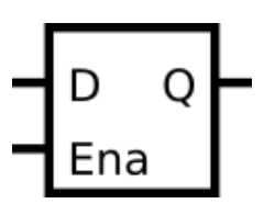
D Latch

锁存器的状态更新依赖于控制信号(如使能信号 EN)的 “电平”,而非 “边沿”(上升沿或下降沿),这是它与触发器最核心的区别。
而触发器仅在时钟信号的特定边沿(如上升沿)才采样输入并更新输出,其他时间无论输入如何变化,输出都保持不变。
电平敏感的敏感列表:
由于锁存器对控制信号的 “电平” 敏感,always块的敏感列表必须包含所有可能触发输出变化的电平信号。
例如,对于 D 锁存器(输入 D、使能 EN、输出 Q),敏感列表需包含EN和D(因为当 EN 为有效电平时,D 的变化会直接影响 Q;当 EN 的电平变化时,也可能导致 Q 锁存或更新),即: always @(EN or D) begin ... end
非阻塞赋值(Non-blocking Assignment):
尽管锁存器是电平敏感,但作为时序元件(有记忆功能),其输出的更新并非 “立即响应” 输入(存在微小的存储延迟)。因此,Verilog 中需用非阻塞赋值(<=) 描述输出更新,以模拟这种 “延迟更新” 的特性,避免竞争条件。
例如:Q <= D;(而非阻塞赋值=,后者会立即更新,不符合时序元件的行为)。
Solution
module top_module (
    input d,
    input ena,
    output q);

    always @(ena or d) begin  //level-sensitive sensitivity lists
        if(ena)
        q <= d;
    end

endmodule
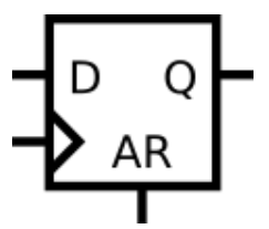
DFF (1)
异步DFF

Solution
module top_module (
    input clk,
    input d,
    input ar,   // asynchronous reset
    output q);

    always @(posedge clk,posedge ar) begin
        if(ar)
            q <= 0;
        else
            q <= d;
    end
endmodule
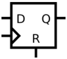
DFF (2)
同步DFF
Solution
module top_module (
    input clk,
    input d,
    input r,   // synchronous reset
    output q);

    always @(posedge clk) begin
        if(r)
            q <= 0;
        else
            q <= d;
    end
endmodule
DFF + gate
Solution
module top_module (
    input clk,
    input in,
    output out);

    always @(posedge clk) begin
        out <= out ^ in;  //out可以同时存在于赋值的两侧
    end
endmodule
Mux and DFF (1)
Solution
module top_module (
    input clk,
    input L,
    input r_in,
    input q_in,
    output reg Q);

    //Mux 2-to-1
    wire mid;
    assign mid = L ? r_in : q_in;

    //DFF 同步
    always @(posedge clk) begin
        Q <= mid;
    end

endmodule
Mux and DFF (2)
Solution
module top_module (
    input clk,
    input w, R, E, L,
    output Q
);
    wire mid1 = E ? w : Q;
    wire mid2 = L ? R : mid1;
    always @(posedge clk) begin
        Q <= mid2;
    end

endmodule
DDFs and gates
Solution
module top_module (
    input clk,
    input x,
    output z
);
    wire Q1;
    wire Q2;
    wire Q3;
    wire mid1;
    wire mid2;
    wire mid3;

    assign mid1 = x ^ Q1;
    assign mid2 = x & ~Q2;
    assign mid3 = x | ~Q3;

    always @(posedge clk) begin
        Q1 <= mid1;
        Q2 <= mid2;
        Q3 <= mid3;
    end

    assign z = ~(Q1 | Q2 | Q3);
endmodule
Create circuit from truth table
Solution
module top_module (
    input clk,
    input j,
    input k,
    output Q);

    always @(posedge clk) begin
        if ((j != k) && (j ^ k == 1))
            Q <= j;
        else if (j == 0)
            Q <= Q;
        else
            Q <= ~Q;
    end
endmodule
Detect an edge
| 精彩的动态过程 |
|---|
检测 8 位输入信号中每个 bit 从 0 到 1 的上升沿变化,并在变化发生后的紧接着的下一个时钟周期将对应输出位置 1。
核心思路:延迟采样 + 边沿检测
- 延迟采样:用寄存器
prev_in保存前一个时钟周期的输入信号in,这样可以对比当前周期和前一周期的数值。 - 边沿检测:对每个 bit,若当前周期是 1 且前一周期是 0,则说明发生了
0→1的上升沿,对应输出位pedge置 1。
Solution
module top_module (
    input clk,
    input [7:0] in,
    output [7:0] pedge
);

    reg [7:0] pre_in;
    always @(posedge clk) begin
        pre_in <= in;
    end
    always @(posedge clk) begin
        pedge <= in & ~pre_in;
        //直观理解:随着时钟的进行,下一个周期将自动(重新检测)回落状态。
    end

endmodule
Official Solution
module top_module(
    input clk,
    input [7:0] in,
    output reg [7:0] pedge);

    reg [7:0] d_last;

    always @(posedge clk) begin
        d_last <= in;            // Remember the state of the previous cycle
        pedge <= in & ~d_last;    // A positive edge occurred if input was 0 and is now 1.
    end

endmodule
Detect both edges
Solution
module top_module (
    input clk,
    input [7:0] in,
    output [7:0] anyedge
);

    reg [7:0] pre_in;
    always @(posedge clk) begin
        pre_in <= in;
        anyedge <= (in & ~pre_in) | (~in & pre_in);
    end

endmodule
Edge capture register
边沿捕获寄存器
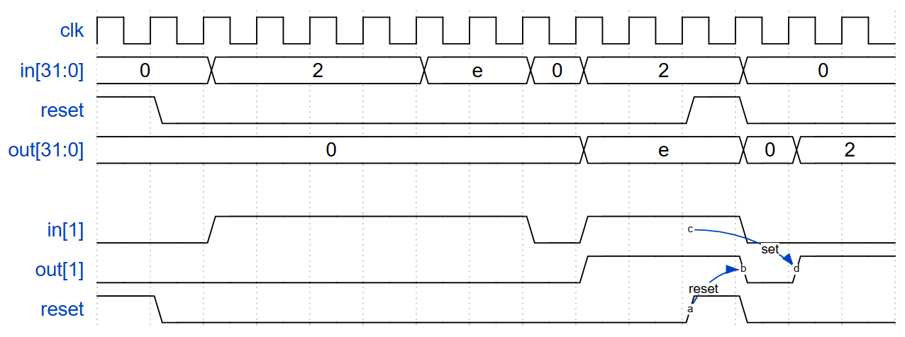
题目:
对于 32 位向量中的每个位,当输入信号在一个时钟周期内从 1 变为下一个时钟周期内的 0 时捕获。“捕获”意味着输出将保持为 1,直到寄存器被复位(同步复位)。
每个输出位的行为类似于 SR 触发器:在发生 1 到 0 的转换后的周期内,应将输出位设置为(1)。当复位为高电平时,应在正时钟沿将输出位复位为(0)。如果上述两个事件同时发生,则复位优先。在下面的示例波形的最后 4 个周期中,“复位(reset)”事件比“设置(set)”事件早一个周期发生,因此这里没有冲突。
在下面的示例波形中,为了清晰起见,再次分别显示了复位、in[1] 和 out[1]。

Solution
module top_module (
    input clk,
    input reset,
    input [31:0] in,
    output [31:0] out
);

    reg [31:0] pre_in;
    always @(posedge clk) begin
        pre_in <= in;
    end

    always @(posedge clk) begin
        if(reset)
            out <= 32'b0;  //同步复位
        else
            out <= (~in & pre_in) | out;
            /**
            1. out是上一周期的输出值;
            2. 若检测到下降沿(~in & in_d 对应位为 1),则无论 out 原值如何,结果为 1(即:置位);
            3. 若未检测到下降沿,则结果等于 out 原值(即保持不变)。
            **/
    end

endmodule
Dual-edge triggered flip-flop
| 巧妙的选择 |
|---|
双向触发触发器
Solution
module top_module (
    input clk,
    input d,
    output q
);

    reg pre_d_pos, pre_d_neg;

    always @(posedge clk) begin
        pre_d_pos <= d;
    end
    always @(negedge clk) begin
        pre_d_neg <= d;
    end

    assign q =  clk ? pre_d_pos : pre_d_neg;
    /**
    clk == 1 时,选择 “d的上一个上升沿的值”;
    clk == 0 时,选择 “d的上一个下升沿的值”;
    即,output 具有“跟随的效果”:clk每跳变一次(无论上跳还是下调),q都将对“d的上一状态(pre_d_pos 或 pre_d_neg)”进行一次跟随。
    **/
endmodule
